Windows XP: “you may be a victim of software counterfeiting”

After updating for Microsoft Windows XP you are prompted with a “Your software is counterfeit” error message at startup. Even after visiting the www.microsoft.com/genuine/ site and validating, you still get the above message popping up after 2 or 3 boots. There is a holow blue star in system tray and the message “you may be a victim of software counterfeiting” appears every few minutes. Desktop wallpaper move into dark color.

There is some solutions to this and I would like you to follow the steps below to fix the issue.

1. Reboot and login with safe mode (press f8 continuously and select safe mode)

2. Navigate to c:\windows\system32\ folder and delete (or rename) following file: wgatray.exe, wgatray.exe, Note: Dllcache is a hidden folder, to view hidden folders do the following, go to Start, Control Panel, Folder Options, Select the view Tab and under the Hidden Files option, select Show hidden files and folders

3. Click on Start, Run and within the open dialog box type regedit and click OK.

* Within the Registry Editor navigate to HKEY_Local_Machine\Software\Microsoft\WindowsNT\CurrentVersion\Winlogon\Notify\WGALOGON

* Right Click and Export the WGALOGON Folder (this should be saved onto your machine for backup purposes)

* After Exporting the folder, DELETE the WGALOGON folder

4. Close all applications and restart your machine back to normal mode

Good luck.

Installation suggestions and use of dial indicators for centrifugal pump

1. Nonferrous shim packs should be installed under all feet of the pump and driver, particularly

when installing a new pump. The amount should be 0.125 to 0.250 in (3.175 to 6.35 mm) in no more than three pieces to start; for example, one 0.125-in (3.175 mm) and two 0.0625-in (1.59-mm) full shims of stainless steel.

2. Motors have four feet generally, and any “soft foot” should be compensated first. A soft

foot is one that is shorter than the other two or three feet, a condition that puts a twist or strain in the equipment. Simply place a dial indicator stem vertically against the motor foot and release the hold-down bolts sequentially around the unit, recording and retightening at each step. If a 0.002-in (0.050-mm) spring-up occurs on three feet, for example, and 0.006 in (0.152 mm) occurs on the fourth foot, add 0.004 in (0.10 mm) of shim to the fourth foot, eliminating the soft foot.

3. Provide low-sag tooling to reach over the coupling (coupling left in place) for reverse

indicator alignment. A 0.001- to 0.0015-in (0.025- to 0.038-mm) sag is easy to accomplish

on indicator reach bars.

4. Let the indicator indicate on its own bracket or bracket pin, thus preventing any poor

surface condition of shaft or coupling from contributing to poor measurements.

5. Support the dial indicator weight on the motor or pump shaft so it does not contribute

to “reach bar” sag.

6. Do not overlook the fact that many times one can clamp to the shaft behind each coupling

hub and obtain more span and therefore better accuracy.

7. Record all data looking the same way down the unit; that is, top east, bottom, west or

top, north bottom, south or top, right bottom, left. It is suggested that the driver-pump

always be viewed from the driver end.

8. Turn the shafts in the direction they normally turn and approach the 90° points in

a precise manner (do not back up and introduce backlash errors). Turning in the normal

direction is good training because, on gear units, it reduces helix angle lift

errors.

Utility Rigging Charts

Wire Rope Slings ASME B30.9

(1) Minimum 10 times the rope diameter between splices or sleeves.

(2) Horizontal sling angles less than 30 degrees should not be used.

(3) All swaged socket and poured socket assemblies shall be proof tested.

(4) Consult manufacturer if temperatures are below 60 degrees F or above 400 degrees F.

(5) Welded end attachments shall be proof tested.

(6) Eyes shall not be formed using knots.

(7) Wire rope clips shall not be used to fabricate slings.

(8) Remove from service if: abrasion, kinking, crushing, heat damage, broken wires

(10 in one lay or 5 in one strand in one lay), distortion, damaged end attachments,

hooks with 15% spread or 10 degree twist.

(9) Slings shall not be used at load greater than rated capacity.

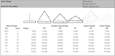
Alloy Steel Chain Slings ASME B30.9

(1) Slings shall not be used at a load greater than rated capacity.

(2) All welded slings shall be proof tested by the sling manufacturer.

(3) Mechanically assembled slings shall be comprised entirely of proof tested components.

(4) Slings shall have permanently affixed identification stating size, grade, rated load and angle on which

the rating is based, reach, number of legs, and sling manufacturer.

(5) Consult mfg. if temperatures are below -40 degrees F or above 600 degrees F.

(6) Attachments or components shall have a rated load equal to the alloy chain.

(7) Slings shall be inspected for damage by a designated person making a record of the conditions, at

least annually.

(8) Repairs shall be made only by the chain mfg. or qualified personnel.

(9) Removal Criteria: missing or illegible sling identification, wear, nicks and gouges, cracked or broken,

bent, weld splatter, heat damage and throat opening or twist in hooks.

Synthetic Web Slings ASME B30.9

(1) Slings shall not be used at a load greater than shown on its tag.

(2) Horizontal angles less than 30 degrees should not be used.

(3) Each sling shall be permanently marked to show: name of the manufacturer, code or stock number,

rated loads for the type of hitches used, any type of synthetic web material.

(4) Reused or welded fittings shall be proof tested 2 times the rated load.

(5) Slings shall be repaired only by a sling manufacturer or qualified person.

(6) Temporary repairs shall not be permitted.

(7) Repaired sling shall be proof tested to two times the rated load.

(8) Periodic inspections should be conducted at least annually, with written inspection records.

(9) Removal Criteria: acid or caustic burns, melting or charring, holes tears, cuts, or snags, broken

or worn stitching, excessive abrasive wear, knots, damaged, cracked or broken fittings.

Utility Rigging Charts

Whenever any sling is used, the following practices shall be observed:

(1) Slings that are damaged or defective shall not be used.

(2) Slings shall not be shortened with knots or bolts or other makeshift devices.

(3) Sling legs shall not be kinked.

(4) Slings shall not be loaded in excess of their rated capacities.

(5) Slings used in a basket hitch shall have the loads balanced to prevent slippage.

(6) Slings shall be securely attached to their loads.

(7) Slings shall be padded or protected from the sharp edges of their loads.

(8) Suspended loads shall be kept clear of all obstructions.

(9) All Employees shall be kept clear of loads about to be lifted and of suspended loads.

(10) Hands and fingers shall not be placed between the sling and its load while the sling is being tightened

around the load

(11) Shock loading is prohibited.

(12) A sling shall not be pulled from under a load when the load is resting on the sling.

(d) Inspections . Each day before being used, the sling and all fastenings and attachments shall be

inspected for damage or defects by a competent person designated by the employer.

Additional inspections shall be performed during sling use, where service conditions warrant. Damaged

or defective slings shall be immediately removed from service.


Overview of Pipe Drafting and Design


In the design of an industrial facility, engineers
develop process flow sheets, set up project specifications
and design or select equipment. The design drafters use
the information supplied by engineers and equipment
vendors and applies the knowledge and experience
gained in the office and field to design and layout the
facility.
In the design and layout of an industrial complex,
thousands of piping drawings are needed to provide
detailed information to the craftsmen who will construct
the facility. Facility design and layout must meet the customer’s
expectations as well as comply with safety codes,
government standards, client specifications, budget, and
start-up date. The piping group has the main responsibility for the
design and layout of the facility. Drafters and designers
must coordinate their efforts with the civil, structural,
electrical, and instrumentation groups throughout the
design process. The piping group must provide each
design group the necessary information needed to complete
their part of the project and have the complete set of
plan and construction drawings finished on time. During
this time, it may be necessary for designers to visit the
plant construction site to establish tie-ins or verify information
necessary to complete the design.

Piping Engineering Leadership for Process Plant Projects by James O. Pennock

There are many books already on the market that address all the purely technical and mechanical aspects of the piping engineering and design profession (piping). There is also a long list of codes and standards that form the "rules" that govern the piping industry. This book is not about these technical aspects of piping nor is it intended to compete with or contradict any of these fine works. In fact, I have a number of these books in my personal library. I have found the need to refer to them on a regular basis during the course of my work. I also have used many of them as text or reference material when I teach the various entry levels and intermediate level design training classes. This book is also not about piping department management. There is no doubt that department management is complex, and the issues there are very important. Some department issues may even be similar to issues discussed in this book. However, I will leave any discussion of the department management area to others.

Download ebook here

Ielts mp3 dowload

Actually, download ebooks from megaupload and Rapid share are quite difficult for those who don't have premium account. There are some better ways to go over that issue and searching from free hosting such as mediafire.com, 4shared.com, box.net...is one of the good way.

By that way, i found a lot of Ielts materials here,

Cheers,

Contract managment software

Microsoft Dynamics™ SL

Streamline time-consuming contract management tasks and increase the productivity of subcontractor interactions for even the most complex projects. By improving control over change orders, document tracking, and subcontractor disbursements, you can help ensure timely completion, enhance cash flow, and boost project profitability.


Manage Contract
documents, change orders, and disbursements to
optimize project cash
flow and profitability.


Control subcontractor
payments, lien waivers, and
pay-when-paid subcontracts.


BENEFITS


Effectively manage subcontract agreements


Create and track agreements from the pending stage through commitment, then manage subcontractor performance by linking payments to the achievement of contractual commitments, including on-time document submittals.


Boost productivity

Increase the profitability of project work and change orders by reviewing budgets, margin, and schedule impacts before work proceeds or changes are approved.

Streamline change order approval and tracking

View, track, and approve change orders easily to help eliminate delays, reduce the risk of miscommunication or unauthorized work, and more quickly turn change orders into billable tasks.


Take control of documentation

Keep on top of compliance documents, drawings, permits, proof of insurance submittals, performance bonds, and other important documents to help prevent lost, late, incomplete, or missing paperwork including tailoring of payment controls for subcontractors based on their insurance policy expirations.


Stay on schedule with automated alerts

Receive prompts about unapproved change orders and pending deadlines for document submittals.