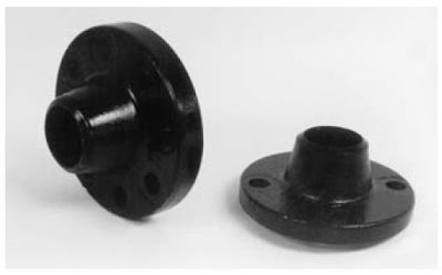
Flanges have been designed and developed to be used in a myriad of applications. Each one has its own special characteristics, and should be carefully selected to meet specific function requirements. The following flanges will be discussed in this chapter:
• weld neck
• threaded
• socket weld
• slip-on
• lap-joint
• reducing
• blind
• orifice
NOTE: A photograph and short description accompanies each flange as well as symbols to depict the flange as it would appear on a drawing. The manual and AutoCAD techniques for creating the drawing symbols are shown for the weld neck flange only. The drawing symbols for the remaining flanges can be created in a similar fashion with only a few minor alterations.
Weld Neck Flange
The weld neck flange shown in Figure -1 is occasionally referred to as the “high-hub” flange. It is designed to reduce high-stress concentrations at the base of the flange by transferring stress to the adjoining pipe. Although expensive, the weld neck flange is the best-designed butt weld flange available because of its inherent structural value and ease of assembly. Known for its strength and resistance to dishing, the weld neck flange is manufactured with a long tapered hub. The tapered hub is created by the gradual increase in metal thickness from the weld joint to the flange facing. The symmetrical taper transition is extremely beneficial under conditions of repeated bending caused by line expansion, contraction, or other external forces.
Figure-2
See Figure-2, for weld neck flange drawing symbols. Weld neck flanges are normally used in severe service applications involving high pressures, high temperatures, or sub-zero conditions. Weld neck flanges are bored to match the ID of the adjoining pipe. In other words, the thinner the wall of the pipe, the larger the bore (hole) through the flange. The thicker the wall of the pipe, the smaller the bore. Because of these matching IDs, there is no restriction to the flow. Turbulence an erosion are therefore eliminated.
Drawing the Weld Neck Flange
Prior to constructing the manual and AutoCAD symbols, certain dimensional information must be provided. These dimensions can be found on the welded fittings–flanges dimensioning chart shown in Figure 3
The figure in this chart represents the raised face weld neck flange.
Notice the three dimensions: O, T, and L. The dimension represents the flange’s OD. The T defines the flange’s face thickness and the L provides the flange’s length or length-thru hub dimension. These three dimensions are required to construct the drawing symbols of each flange. To find the numerical values for these dimensions, locate the appropriate pound rating section, that is, 150# 300#, etc. Find the proper size pipe in the Nominal Pipe Size column. Follow across the chart to determine the O, T, and L dimensions. For our demonstration, we will be using a 14-300# raised face weld neck (RFWN) flange. You should find the O, T, and L measurements for this flange to be 23_, 2 _, and 5 _ respectively.
Two step-by-step methods will be presented for constructing the weld neck flange. Figure bellow demonstrates steps using manual drafting techniques. This figure presents the steps using AutoCAD commands.


0 comments:
Post a Comment